
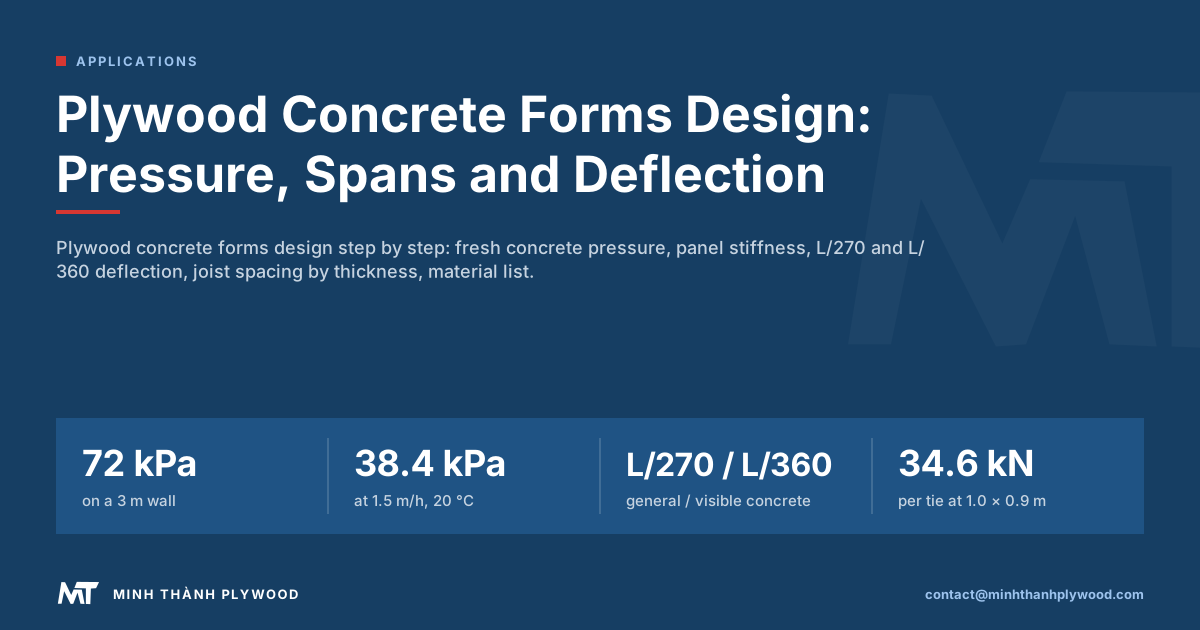
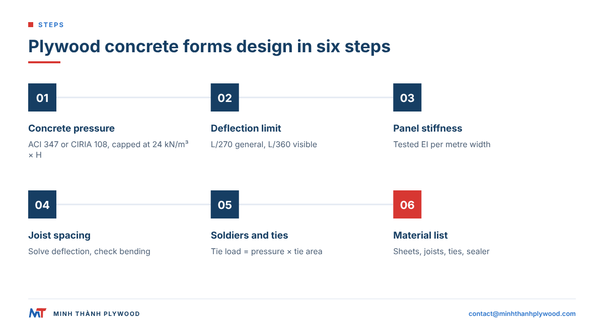
Plywood concrete forms design follows one chain: work out the pressure of fresh concrete, treat the plywood as a beam spanning between joists, and space the joists so the panel stays inside its deflection and bending limits. A worked wall example below lands at 300 mm joist centres for 18 mm film-faced plywood. Minh Thanh Plywood supplies 12–21 mm formwork panels and quotes them against your drawing.
What does plywood concrete forms design have to decide?
Plywood concrete forms design decides three numbers. The first is the pressure the fresh concrete puts on the form face. The second is the panel thickness that carries it. The third is the spacing of the joists, soldiers and ties behind that panel. Everything else, from the material list to the order you send a mill, follows from those three.
The chain runs in one direction. Pressure comes first, because it depends on the wall height, the pour rate, the concrete temperature and the mix. The plywood then acts as a continuous beam over the joists, so its stiffness and the joist spacing set how far it bows. The joists in turn span between soldiers or walers, and the ties hold the two faces of the wall together.
A designer can fix the panel and solve for the joist spacing, or fix the joist spacing of an existing system and solve for the panel. Most site teams do the first: they pick a standard sheet such as 18 mm film-faced plywood and space the joists to suit it.
How much pressure does fresh concrete put on a form?
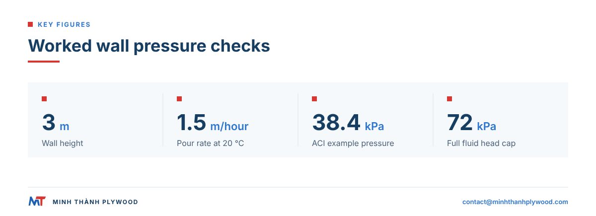
Fresh concrete presses on a form like a heavy liquid until it starts to stiffen. The upper limit is the full fluid head: about 24 kN/m³ for normal-weight concrete multiplied by the height of fresh concrete. A 3 m wall filled faster than it can set loads its base at about 72 kPa.
The figure of 24 kN/m³ comes from a density of about 2,400 kg/m³ times gravity. Lightweight mixes press less, heavy mixes more. Five things push the real pressure toward or away from that limit:
- Pour rate. The faster the form fills, the more of the column is still liquid.
- Concrete temperature. Cold concrete sets slowly and presses harder.
- Mix and workability. Self-compacting concrete and high-slump mixes act close to a true liquid.
- Retarders and cement type. Slower setting keeps more of the column fluid.
- Vibration. Internal vibration re-liquefies the mix around the poker.
Self-compacting concrete, fast pours and retarded mixes are designed at the full fluid head. Conventional mixes placed at a known rate can use the formulas below.
Which formula gives the design pressure: ACI 347 or CIRIA 108?
North American designers use ACI 347R-14, and UK and many European designers use CIRIA Report 108 with the temporary works rules of BS 5975; both cap the result at the full fluid head. For an ordinary wall the ACI metric formula is short enough to run on site.
For walls up to 4.2 m high placed at less than 2.1 m per hour, and for columns, ACI 347R-14 gives:
Pmax = Cw × Cc × [7.2 + 785R ÷ (T + 17.8)] kPa
where R is the rate of rise in m per hour, T the concrete temperature in °C, Cw the unit-weight coefficient (1.0 for normal-weight concrete) and Cc the chemistry coefficient (1.0 for ordinary cements without retarders). The result is never taken below 30 Cw kPa and never above the full fluid head. Faster wall pours, between 2.1 and 4.5 m per hour, use a second formula with an extra temperature term.
CIRIA 108 reaches a comparable number through pour rate, temperature, concrete constituents and form height. The two methods give different values for the same pour, so use the one your project’s temporary works rules name and do not mix them inside one calculation.
Worked example: how do you calculate the pressure on a 3 m wall?
A 3 m wall of normal-weight concrete, poured at 1.5 m per hour at 20 °C, gives a design pressure of about 38.4 kPa under the ACI formula, roughly half the full fluid head of 72 kPa. That number drives every later step of the example.
The working, with Cw = 1.0 and Cc = 1.0:
- 785 × 1.5 = 1,177.5.
- 20 + 17.8 = 37.8.
- 1,177.5 ÷ 37.8 = 31.2.
- 7.2 + 31.2 = 38.4 kPa.
- Check the floor: 38.4 kPa is above 30 kPa, so it stands.
- Check the cap: the full fluid head is 24 × 3 = 72 kPa, so 38.4 kPa governs.
Double the pour rate to 3 m per hour and the wall moves into the faster-pour formula, with a markedly higher result. Drop the concrete temperature in winter and the pressure rises again. The pour plan and the form design belong together: a designer who knows the site will pour slowly can use a lighter panel layout.
Plywood formwork design: how does the panel carry the load?
The plywood face acts as a beam running across the joists, one metre-wide strip at a time. Two properties decide how well it does that job: its stiffness, which controls how far it bows, and its bending strength, which controls when it breaks. Stiffness almost always governs formwork spans.
For a strip one metre wide, the gross second moment of area is 1,000 × t³ ÷ 12, so stiffness grows with the cube of the thickness. Going from 12 mm to 18 mm more than triples it, from 144,000 to 486,000 mm⁴ per metre of width. Bending strength grows with the square of the thickness, through the section modulus 1,000 × t² ÷ 6.
Plywood is not a solid block of timber: the plies that run across the span add little stiffness in that direction. Panel properties for design therefore come as effective values in each direction, from the panel’s standard or test report. APA publishes Plyform section properties for this reason, and an engineer designing with an imported film-faced panel asks the supplier for the equivalent tested figures before finalising the spans.
Which way should the face grain run across the joists?
Run the face grain of the plywood across the joists, at right angles to them, because a sheet spanning parallel to its face grain is stronger and stiffer than one turned the other way. On standard sheets of 1220 × 2440 mm, that means the long edge of the sheet crosses the joists.
The outer plies of a plywood sheet run along its length, and the outer plies carry most of the bending. Turned with the face grain parallel to the joists, the same sheet spans on its weaker axis and needs closer supports for the same pressure. On a wall form the joists usually stand vertical, so the sheets lie with their long side horizontal; on a slab the sheets run across the secondary beams.
Mark the face grain direction on the formwork drawing and on cut panels. A cut-to-size set of formwork panels arrives with its face direction written on the cutting list, so the crew does not have to guess on the deck.
What deflection limit should plywood formwork meet: L/270 or L/360?
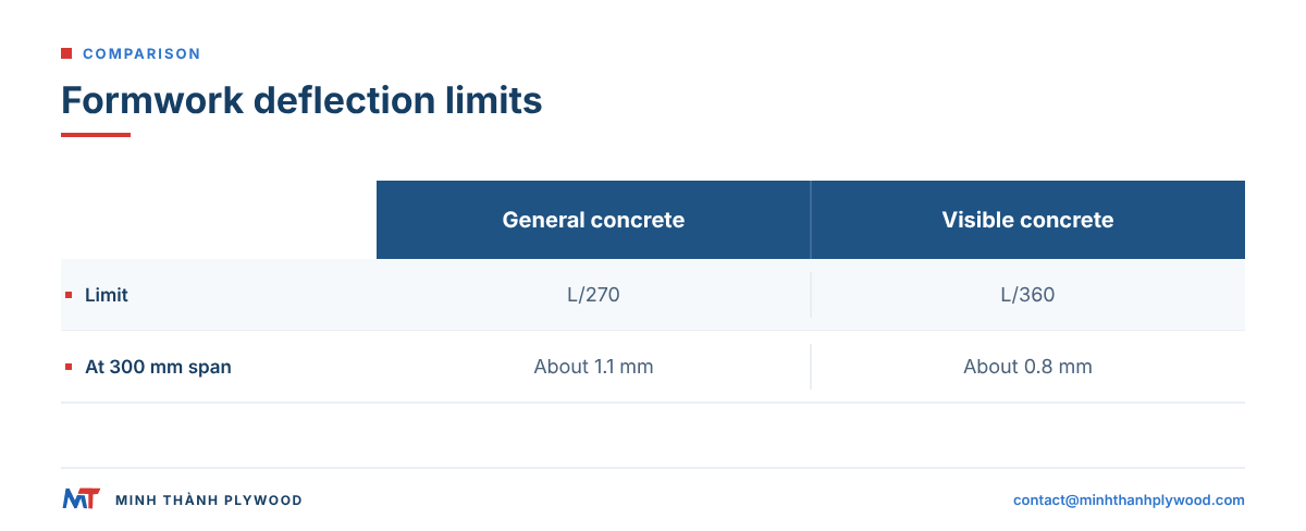
Plywood formwork is commonly designed to deflect no more than span ÷ 270 for general concrete and span ÷ 360 where the concrete stays visible. The APA concrete forming guidance (consulted 20 October 2026) uses these two limits for its Plyform pressure tables.
On a joist spacing of 300 mm, span ÷ 270 allows about 1.1 mm of bow between joists and span ÷ 360 about 0.8 mm. Those small numbers are why fair-faced walls look flat: a panel that bows 3 mm between every joist prints a quilted pattern into the concrete that shows in raking light.
Deflection for a panel continuous over three or more joists is about 0.0069 × w × L⁴ ÷ EI, where w is the load per metre of strip, L the joist spacing and EI the panel’s effective stiffness. A panel that spans only between two joists bows almost twice as far, about 0.013 × w × L⁴ ÷ EI, so short single-span offcuts deserve closer support.
The same wall in US units
For a US drawing the same chain runs in feet and psf. The ACI 347 wall formula in imperial units is p = 150 + 9,000 R / T, in psf, with the pour rate R in ft/h and the concrete temperature T in °F. A 10 ft wall poured at 5 ft/h at 68 °F gives 150 + 9,000 x 5 / 68 = about 812 psf, the same pressure as the 38.4 kPa above (about 802 psf), against a full fluid head of 150 pcf x 10 ft = 1,500 psf. The lower figure governs.
How do you work out joist spacing for each plywood thickness?
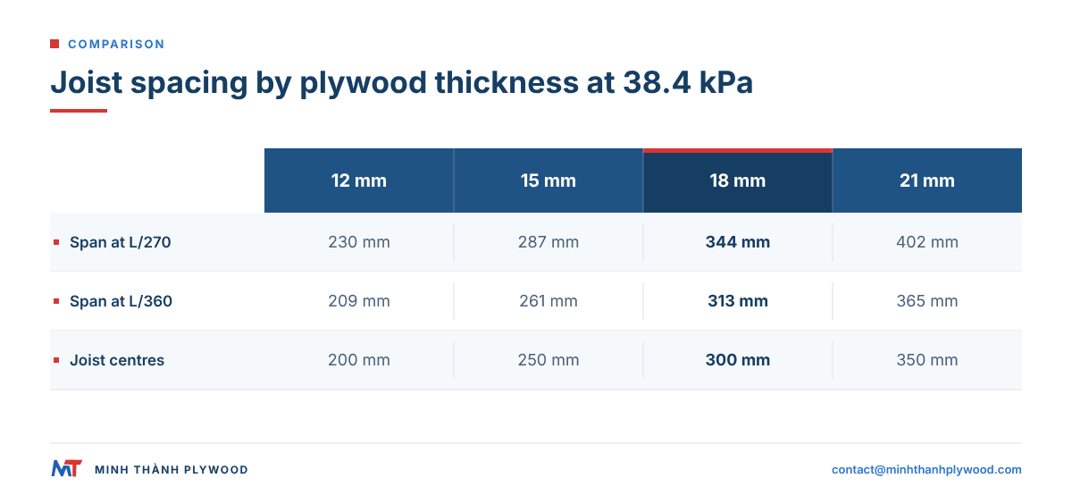
Solve the deflection formula for L: the joist spacing at which the panel just reaches its limit. At the worked example’s 38.4 kPa, and with an illustrative effective stiffness, 18 mm plywood reaches span ÷ 360 at about 313 mm, so practical joist centres of 300 mm work.
The table uses the gross section of each thickness and an illustrative effective modulus of 6,000 N/mm², continuous over three or more spans. It shows how the spacing moves with thickness; it is not a design table for any one product.
| Plywood thickness | Gross I per metre width | Span at L/270 | Span at L/360 | Practical joist centres |
|---|---|---|---|---|
| 12 mm | 144,000 mm⁴ | about 230 mm | about 209 mm | 200 mm |
| 15 mm | 281,250 mm⁴ | about 287 mm | about 261 mm | 250 mm |
| 18 mm | 486,000 mm⁴ | about 344 mm | about 313 mm | 300 mm |
| 21 mm | 771,750 mm⁴ | about 402 mm | about 365 mm | 350 mm |
At those spans the bending stress in each panel comes out at about 8.4 N/mm². Your engineer compares that with the design bending strength of the chosen panel, then repeats both checks with the project’s real pressure and the supplier’s tested stiffness. The pattern holds whatever the inputs: each 3 mm of extra thickness buys roughly 50 mm of joist spacing.
Joist spacing for US panel thicknesses
Inch sizes convert at exactly 25.4 mm to the inch (NIST). The same method, at 802 psf (38.4 kPa) and the same illustrative modulus, gives these spans for the US thicknesses:
| Plywood thickness | Span at L/270 | Span at L/360 | Practical joist centres |
|---|---|---|---|
| 1/2 in (12.7 mm) | about 9.6 in | about 8.7 in | 8 in |
| 5/8 in (15.9 mm) | about 12.0 in | about 10.9 in | 10 in |
| 3/4 in (19.1 mm) | about 14.3 in | about 13.0 in | 12 in |
| 1-1/8 in (28.6 mm) | about 21.5 in | about 19.5 in | 18 in |
These are method illustrations. A US designer takes the allowable stress and rolling shear values for the panel from APA’s Concrete Forming Design/Construction Guide, Form V345, which lists capacities for Plyform by class and thickness.
How does plywood shuttering design differ for slabs?
Plywood shuttering design for slabs and soffits starts from vertical load instead of lateral pressure: the weight of the wet slab, the formwork itself and the construction live load. A 200 mm slab of normal-weight concrete weighs about 4.8 kPa before anyone walks on it. In US practice the dead load is 12.5 psf for each inch of slab thickness (APA, concrete forming). An 8 in slab therefore loads the deck with 100 psf of concrete before the live load.
ACI 347 sets minimums for that live load: at least 2.4 kPa for workers, equipment and placing, and a combined dead and live load of at least 4.8 kPa. Where motorised carts run on the deck, the minimums rise to 3.6 kPa and 6.0 kPa. Add the self-weight of the form and the result is the load per square metre the soffit panel carries.
Slab panels usually span between secondary beams at closer centres than wall joists, because the soffit face of a slab is often left exposed. 15 mm film-faced plywood is the common choice for closely supported slab soffits, with 18 mm where the beam spacing is wider. The same deflection check applies, with w now the vertical load.
Which Plyform grade goes into a design: Class I, Structural I, HDO or MDO?
US designs name Plyform by grade. Class I has Group 1 faces for high strength and stiffness; Structural I uses Group 1 species throughout for the highest load capacity and is the choice for engineered forms, with the face grain across the supports. Either can be ordered with an HDO or MDO overlay. HDO gives the smoothest finish and the most reuses, up to 200 or more with proper care.
Plyform is made to the tolerances of PS 1 on thickness, width, length, squareness and edge straightness. APA’s guide A236 explains why code-compliant formwork follows PS 1 under ACI 318 and ACI 347 as the International Building Code requires (APA). Design pressures, framing spans, section properties and bending radii for curved forms come from Form V345.
Job-built forms. On small jobs, crews build forms from a 3/4 in plywood face and 2x4 walers. Snap ties with a self-centering loop and brackets that hook the tie and hold the 2x4 are common, with ties typically at 16 x 24 in on walls and 1/4 in pencil rod to tie form units together (Surebuilt). At 802 psf a 16 x 24 in tie grid, 2.67 ft2, loads each tie with about 2,140 lb, which is the figure to compare with the snap tie’s rated load.
What tie and soldier spacing follows from the pressure?
Each tie carries the pressure acting on its share of the wall, so the tie load equals the design pressure multiplied by the horizontal and vertical tie spacing. At 38.4 kPa, a tie at 1.0 m by 0.9 m centres carries about 34.6 kN, and the chosen tie must have a safe working load above that.
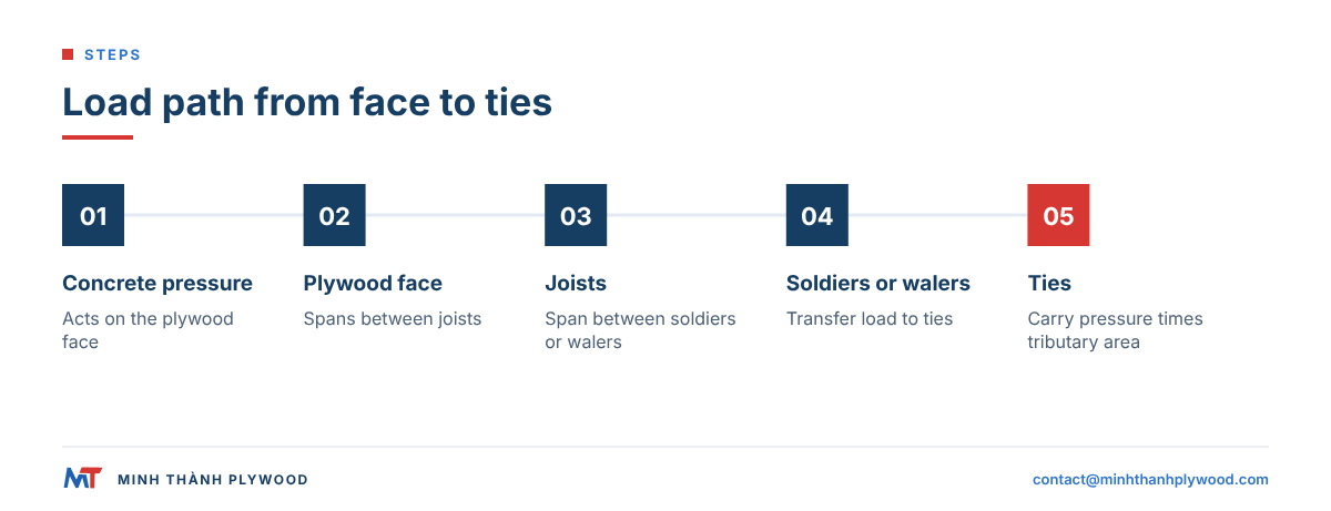
The same pressure flows through the system in steps: plywood to joists, joists to soldiers or walers, soldiers to ties. Each member is checked for bending and deflection at its own span. Joists span between soldiers, soldiers span between ties, and the tie spacing is usually what a designer adjusts to match the tie’s rated load.
Tie holes print on the concrete. On visible walls the tie grid is drawn on the elevation with the sheet joints, so ties fall on a regular pattern. The guide to plywood for fair-faced concrete covers the layout side of that decision.
What are the requirements of good formwork?
Good formwork carries the concrete pressure and site loads safely and stays within its deflection limit. It keeps joints grout-tight and holds the line and level on the drawing. It strips without damaging the concrete or the panel, and comes back for the next pour. A design that meets the first two and fails the rest still costs money.
The requirements, in the order a site checks them:
- Strength. Every member and tie carries its load with the safety factor the temporary works rules require.
- Stiffness. The face stays inside span ÷ 270, or span ÷ 360 where the concrete stays visible.
- Tight joints. Sheet joints and tie holes do not leak grout.
- Accuracy. The form holds the dimensions, line and plumb of the drawing.
- Easy stripping. Release agent and panel face let the form come away cleanly.
- Reuse. Panels and members survive handling for the planned number of pours.
- Safe access. Platforms, guardrails and bracing are part of the design.
US sites work under OSHA’s concrete formwork rule, OSHA standard 1926.703, which requires formwork to carry all intended vertical and lateral loads.
How do you choose the panel thickness for a formwork design?
Choose the thinnest panel that meets the deflection limit at a joist spacing your system can provide. Use 12 mm for supported liners, 15 mm for closely supported slab soffits, 18 mm for walls and columns, and 21 mm for heavier components or wider joist centres. Thicker panels also survive more handling.
Weight is the other side of the choice. An 18 mm sheet of 1220 × 2440 mm weighs about 34.8–40.2 kg on an Eucalyptus core and about 31.1 kg on Acacia, and a crew lifts every sheet by hand on many sites. Moving from 18 mm to 21 mm adds stiffness and spacing, but also adds weight per lift.
Thickness interacts with tolerance as well. Our film-faced sheets hold ±0.5 mm on thickness and ±2 mm on length and width, so adjoining panels on a wall sit flush and the joist layout drawn for 18 mm works across the whole delivery. The guide to 18 mm film faced plywood covers the standard wall panel in detail.
What goes on a plywood shuttering material list?
A plywood shuttering material list starts from the contact area of concrete, converts it to sheets with a cutting allowance, and then counts the members, ties and consumables the design calls for. A 10 m wall 3 m high, formed on both faces, has 60 m² of contact area.
Worked takeoff for that wall, on 1220 × 2440 mm sheets of 2.98 m² each:
| Item | Quantity basis | Example quantity |
|---|---|---|
| Plywood sheets | 60 m² ÷ 2.98 m², plus about 10% cutting allowance | 23 sheets |
| Joists | Wall length ÷ joist centres, per face | 34 per face at 300 mm |
| Soldiers or walers | Per design spacing, per face | From the drawing |
| Ties with cones and washers | Wall area ÷ tie grid | 34 at 1.0 m × 0.9 m |
| Release agent | Contact area per pour | 60 m² per pour |
| Edge sealer | Every cut edge and drilled hole | All cuts |
| Fixings, chamfer and filler strips | Per joint and corner | From the drawing |
A slab of 100 m² needs about 34 sheets before allowance and 37 with it. Count props, beams and edge forms from the shoring layout.
What should you send a mill with your formwork design?
Send the mill the panel thickness, sheet size, film grade, core, glue bond and edge sealing your design assumes, plus the quantity and destination port, and attach the formwork drawing if it names a stiffness or strength value. A quotation that repeats each of those lines is one you can check against the design.
Minh Thanh Plywood makes film-faced formwork plywood 12–21 mm thick on Eucalyptus or Acacia cores, with 120–135 g/m² standard film or premium film from 135 g/m², and melamine-fortified or phenolic WBP glue. Standard panels give about 12–15 uses and phenolic WBP panels up to about 25, with proper handling, release agent and edge sealing.
The minimum order is one 40HC, with mixed thicknesses by agreement; an 18 mm container holds 795 sheets on Eucalyptus or 880 on Acacia. Production takes 15–45 days after the 30% deposit. Compare your options in the concrete form plywood buying guide, see the US grade system in Plyform classes and sizes, or go straight to the film faced plywood product page.
Specification line to send: “Film-faced plywood for wall formwork, 18 mm, 1220 × 2440 mm, Eucalyptus core, phenolic WBP glue, premium film from 135 g/m², black, sealed edges, export packs, 1 × 40HC to [port]; design assumes joists at 300 mm centres.” Send it through the contact form or WhatsApp +84 988 586 601; we reply within hours.
Buyer questions, answered
How do you calculate the pressure of concrete on formwork?
Start from the full fluid head: concrete unit weight, about 24 kN/m³, times the height of fresh concrete. For a conventional mix placed slowly, ACI 347R-14 gives a lower design pressure from pour rate and temperature, never above that full head.
What is the formwork calculation formula for a wall?
For ordinary walls up to 4.2 m high poured below 2.1 m per hour, ACI 347R-14 uses Pmax = Cw × Cc × [7.2 + 785R ÷ (T + 17.8)] kPa, with a floor of 30 Cw kPa and a cap at the full fluid head.
What deflection limit is used for plywood formwork?
APA concrete forming tables use span ÷ 360 for architectural concrete and span ÷ 270 for general forming. The stricter limit applies wherever the concrete face stays visible.
How far apart should joists be under 18 mm plywood formwork?
In the worked wall example at 38.4 kPa, 18 mm plywood reaches its span ÷ 360 limit at about 313 mm, so joists at 300 mm centres work. Your engineer repeats the check with the real pressure and the panel's tested stiffness.
Which way should the face grain run on plywood formwork?
Run the face grain across the joists, so the panel spans in its stronger and stiffer direction. Turning the sheet the other way cuts its usable span noticeably for the same pressure.
What thickness of plywood is used for concrete forms?
Formwork panels run from 12 mm for supported liners to 21 mm for heavy components; 15 mm suits closely supported slab soffits and 18 mm is the usual wall and column panel.
What are the requirements of good formwork?
Good formwork carries the concrete pressure and site loads safely, stays within its deflection limit, keeps joints grout-tight, holds the line and level of the drawing, strips without damage and can be reused.
What goes on a plywood shuttering material list?
Plywood sheets with a cutting allowance, joists and soldiers or walers, ties with cones and washers, props or shores, release agent, edge sealer for cut edges, fixings and chamfer or filler strips.
What live load is used for slab formwork design?
ACI 347 sets a construction live load of at least 2.4 kPa and a combined dead and live load of at least 4.8 kPa, rising to 3.6 kPa and 6.0 kPa where motorised carts run on the deck.
Does Minh Thanh Plywood design formwork?
No. The temporary works designer owns the design. We supply 12–21 mm film-faced panels in 1220 × 2440 or 1250 × 2500 mm sheets and quote them line by line against the drawing.